- 您现在的位置:买卖IC网 > Sheet目录343 > MIC5018YM4 TR (Micrel Inc)IC DRIVER MOSFET HI SIDE SOT143
�� �
�
�Micrel,� Inc.�
�Application� Information�
�Supply� Bypass�
�A� capacitor� from� VS� to� GND� is� recommended� to� control�
�switching� and� supply� transients.� Load� current� and� supply�
�lead� length� are� some� of� the� factors� that� affect� capacitor�
�size� requirements.�
�A� 4.7μF� or� 10μF� aluminum� electrolytic� or� tantalum�
�capacitor� is� suitable� for� many� applications.�
�The� low� ESR� (equivalent� series� resistance)� of� tantalum�
�capacitors� makes� them� especially� effective,� but� also�
�makes� them� susceptible� to� uncontrolled� inrush� current�
�from� low� impedance� voltage� sources� (such� as� NiCd�
�MIC5018�
�Standard� MOSFET�
�Standard� MOSFETs� are� fully� enhanced� with� a� gate-to-�
�source� voltage� of� about� 10V.� Their� absolute� maximum�
�gate-to-source� voltage� is� ±20V.�
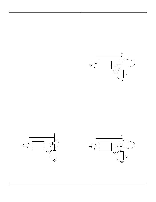
�With� a� 5V� supply,� the� MIC5018� produces� a� gate� output�
�of� approximately� 15V.� Figure� 2� shows� how� the� remaining�
�voltages� conform.� The� actual� drain-to-source� voltage�
�drop� across� an� IRFZ24� is� less� than� 0.1V� with� a� 1A� load�
�and� 10V� enhancement.� Higher� current� increases� the�
�drain-to-source� voltage� drop,� increasing� the� gate-to-�
�source� voltage.�
�+5V�
�VS�
�G�
�10V�
�C� T� L� GND�
�5V�
�batteries� or� automatic� test� equipment).� Avoid�
�instantaneously� applying� voltage,� capable� of� high� peak�
�current,� directly� to� or� near� tantalum� capacitors� without�
�additional� current� limiting.� Normal� power� supply� turn-on�
�(slow� rise� time)� or� printed� circuit� trace� resistance� is�
�usually� adequate� for� normal� product� usage.�
�MOSFET� Selection�
�4.7� μ� F�
�Logic�
�High�
�MIC5018�
�4� 1�
�Voltages� are� approximate�
�*� International� Rectifier�
�standard� MOSFET�
�2� 3� 15V�
�IRFZ24*� approx. 0� V�
�To� demonstrate�
�this� circuit,� trya�
�2� ,� 20W�
�load� resistor.�
�The� MIC5018� is� designed� to� drive� N-channel�
�enhancement� type� MOSFETs.� The� gate� output� (G)� of�
�the� MIC5018� provides� a� voltage,� referenced� to� ground,�
�that� is� greater� than� the� supply� voltage.� Refer� to� the�
�“Typical� Characteristics:� Gate� Output� Voltage� vs.� Supply�
�Voltage”� graph.�
�The� supply� voltage� and� the� MOSFET� drain-to-source�
�voltage� drop� determine� the� gate-to-source� voltage.�
�V� GS� =� V� G� –� (V� SUPPLY� –� V� DS� )�
�where:�
�V� GS� =� gate-to-source� voltage� (enhancement)�
�V� G� =� gate� voltage� (from� graph)�
�V� SUPPLY� =� supply� voltage�
�V� DS� =� drain-to-source� voltage�
�(approx.� 0V� at� low� current,� or� when� fully� enhanced)�
�V� S� U� P� P� L� Y�
�Figure� 2.� Using� a� Standard� MOSFET�
�The� MIC5018� has� an� internal� zener� diode� that� limits� the�
�gate-to-ground� voltage� to� approximately� 16V.�
�Lower� supply� voltages,� such� as� 3.3V,� produce� lower�
�gate� output� voltages� which� will� not� fully� enhance�
�standard� MOSFETs.� This� significantly� reduces� the�
�maximum� current� that� can� be� switched.� Always� refer� to�
�the� MOSFET� data� sheet� to� predict� the� MOSFET’s�
�performance� in� specific� applications.�
�Logic-Level� MOSFET�
�Logic-level� N-channel� MOSFETs� are� fully� enhanced� with�
�a� gate-to-source� voltage� of� approximately� 5V� and�
�generally� have� an� absolute� maximum� gate-to-source�
�voltage� of� ±10V.�
�+3.3V�
�VS�
�G�
�C� T� L� GND�
�2�
�4�
�MIC5018�
�VS� G�
�C� T� L� GND�
�3�
�1�
�V� G� G�
�V� G� S�
�V� LOAD�
�D�
�S�
�V� D� S�
�4.7� μ� F�
�Logic�
�High�
�MIC5018�
�2� 3�
�4� 1�
�Voltages� are� approximate�
�*� International� Rectifier�
�logic-level� MOSFET�
�9V�
�5.7� V�
�3.3� V�
�IRLZ44*� approx. 0� V�
�To� demonstrate�
�this� circuit,� try�
�5� ,� 5W� or�
�47� ,� 1/4W�
�load� resistors.�
�Figure� 1.� Voltages�
�The� performance� of� the� MOSFET� is� determined� by� the�
�gate-to-source� voltage.� Choose� the� type� of� MOSFET�
�according� to� the� calculated� gate-to-source� voltage.�
�Figure� 3.� Using� a� Logic-Level� MOSFET�
�Refer� to� Figure� 3� for� an� example� showing� nominal�
�voltages.� The� maximum� gate-to-source� voltage� rating� of�
�a� logic-level� MOSFET� can� be� exceeded� if� a� higher�
�April� 2006�
�6�
�M9999-042406�
�(408)� 955-1690�
�发布紧急采购,3分钟左右您将得到回复。
相关PDF资料
MIC5020YM
IC DRIVER MOSF LO SIDE HS 8-SOIC
MIC5021YN
IC DRIVER MOSFET HI SIDE HS 8DIP
MIC5400BWM
IC LED DRIVER RGB 28-SOIC
MKP1V240RL
SIDAC BIDIR 0.9A 240V DO-41
MKP3V240RL
SIDAC BIDIRECT 1A 240V DO-201AD
MKP9V160RL
SIDAC BIDIR 0.9A 160V DO-41
MNC-8085
CABINET MEGA NETWORK 31X25X12"
MORPH-IC-II
MODULE USB TO FPGA
相关代理商/技术参数
MIC5018YM4TR
制造商:Micrel 功能描述:MOSFET Driver 1-Out Hi Side Non-Inv
MIC5018YM4-TR
功能描述:IC DRIVER MOSFET HI SIDE SOT143 制造商:microchip technology 系列:IttyBitty? 包装:剪切带(CT) 零件状态:有效 驱动配置:高压侧 通道类型:单路 驱动器数:1 栅极类型:N 沟道 MOSFET 电压 - 电源:2.7 V ~ 9 V 逻辑电压?- VIL,VIH:0.8V,2.4V 电流 - 峰值输出(灌入,拉出):- 输入类型:非反相 高压侧电压 - 最大值(自举):- 上升/下降时间(典型值):- 工作温度:-40°C ~ 85°C(TA) 安装类型:表面贴装 封装/外壳:TO-253-4,TO-253AA 供应商器件封装:SOT-143 标准包装:1
MIC5019
制造商:MICREL 制造商全称:Micrel Semiconductor 功能描述:Ultra-Small High-Side N-Channel MOSFET Driver with Integrated Charge Pump
MIC5019_EB
制造商:MICREL 制造商全称:Micrel Semiconductor 功能描述:Ultra-Small High-Side N-Channel MOSFET Driver with Integrated Charge Pump
MIC5019YFT
制造商:MICREL 制造商全称:Micrel Semiconductor 功能描述:Ultra-Small High-Side N-Channel MOSFET Driver with Integrated Charge Pump
MIC5019YFT EV
功能描述:电源管理IC开发工具 Ultra-Small High Side MOSFET Driver - Evaluation Board
RoHS:否 制造商:Maxim Integrated 产品:Evaluation Kits 类型:Battery Management 工具用于评估:MAX17710GB 输入电压: 输出电压:1.8 V
MIC5019YFT T5
功能描述:功率驱动器IC Ultra-Small High Side MOSFET Driver
RoHS:否 制造商:Micrel 产品:MOSFET Gate Drivers 类型:Low Cost High or Low Side MOSFET Driver 上升时间: 下降时间: 电源电压-最大:30 V 电源电压-最小:2.75 V 电源电流: 最大功率耗散: 最大工作温度:+ 85 C 安装风格:SMD/SMT 封装 / 箱体:SOIC-8 封装:Tube
MIC5019YFT TR
功能描述:功率驱动器IC Ultra-Small High Side MOSFET Driver
RoHS:否 制造商:Micrel 产品:MOSFET Gate Drivers 类型:Low Cost High or Low Side MOSFET Driver 上升时间: 下降时间: 电源电压-最大:30 V 电源电压-最小:2.75 V 电源电流: 最大功率耗散: 最大工作温度:+ 85 C 安装风格:SMD/SMT 封装 / 箱体:SOIC-8 封装:Tube